Wednesday, February 10, 2016
Dasar Elektronika (2) : Komponen Aktif dan Pasif
Dasar Elektronika (1) : Komponen analog dan digital
Elektronika digital hanya mengenal dua kondisi yaitu kondisi "nol" dan kondisi "satu". Namun, kondisi "nol" tidak selalu bernilai 0 volt. Istilah lain dari “kondisi” dalam elektronika digital adalah “logic” (baca : logika).Logic 0 juga dikenal dengan keadaan “Low (L)” atau False (F)” dan logic 1 adalah keadaan “High (H)” atau “True (T)”. Dengan demikian, perbedaan antara elektronika analog dan elektroika digital terletak pada input yang diolah dan output yang dihasilkan, linearitas nilai input dan output, bentuk gelombang, dan flexibilitas tegangan sumber sehingga komponen elektronika yang digunakan pun berbeda. Rangkaian elektronika yang digunakan dalam sistem kendali sebuah robot pada umumnya merupakan rangkaian elektronika yang tersusun dari gabungan komponen-komponen analog dan digital.
Tuesday, February 9, 2016
Robot cerdas karena apa ?
Pernah mendengar istilah robot cerdas? Apakah berbeda antara robot (biasa) dengan robot cerdas ? Kalau ada robot (yang) cerdas, lantas robot lain (yang tidak cerdas) disebut robot apa ya?
Fungsi robot sebagai sebuah alat yang dapat membantu pekerjaan manusia dapat dibedakan berdasarkan kendalinya. Ada yang harus di bawah kendali manusia. Ada juga yang dapat menjalankan fungsinya secara otomatis tanpa harus dikendalikan oleh manusia. Jenis yang terakhir inilah yang dinamakan robot cerdas.
Robot cerdas dilengkapi sebuah sistem kendali sehingga robot dapat menjalankan fungsinya tanpa dikendalikan manusia. Sistem kendali seperti ini biasa disebut dengan sistem cerdas atau kecerdasan buatan (artificial intellegent). Dewasa ini, sistem cerdas sebuah robot berupa program yang ditanamkan pada sebuah chip mikrokontroler/ mikroprosesor.
Robot yang menggunakan mikrokontroler/ mikroprosesor dikenal dengan sebutan robot mikro. Namun demikian, robot cerdas juga bisa berupa robot analog (tanpa mikrokontroler atau mikroprosesor). Sistem kendalinya bukan berupa program melainkan berupa rangkaian elektronika yang dirancang agar robot dapat 'bertugas otomatis'.
Sunday, February 7, 2016
Apa bedanya robot dan robotika?
Bicara soal robot, pasti kita juga sering mendengar istilah robotika. Pertanyaannya, apakah robotika dan robot itu sama? Bagaimana keterkaitan antara robot dan robotika?
Setelah mengenal robot, kita tahu bahwa robot adalah benda atau barang, sedangkan robotika diartikan sebagai adalah satu cabang teknologi yang berhubungan dengan desain, konstruksi, operasi, disposisi struktural, pembuatan, dan aplikasi dari robot.
Robotika adalah cabang ilmu yang mempelajari semua hal terkait dengan teknologi robot. Sebuah robot, telah kita ketahui, tersusun dari tiga bagian : mekanik, kendali dan penggerak. Bidang mekanik sebuah robot dipelajari dalam pembahasan mekanika. Unit kendali robot biasanya berupa rangkaian-rangkaian elektronik baik itu yang dapat diprogram maupun tidak. Sedangkan unit penggerak robot biasanya berupa motor.
Cabang ilmu robotika meliputi pengetahuan bidang elektronika, mesin, mekanika, dan pemrograman (kecerdasan buatan). Oleh karena itu, jika kita berminat menjadi seorang ahli di bidang robotika, kita tidak perlu menjadi ahli di semua bidang (elektronika, mekanika, dan pemrograman untuk kontrol). Kita harus memahami dasar dan konsep secara umum, tetapi kita bisa mengambil peran menjadi ahli dari salah satu bidang pengetahuan tersebut. Think global but become specialist. Apakah kita lebih suka dan mampu di bidang elektronika, mekanika, atau pemrogramannya.
Berbagai Jenis Robot
(http://id.wikipedia.org/wiki/Robot,2010)
1. Robot Mobile
2. Robot Manipulator
3. Robot Humanoid
4. Flying Robot
5. Robot Berkaki
6. Robot jaringan
7. Robot Animalia
Robot jenis ini merupakan robot yang paling banyak dipelajari dan dibuat dalam tahap belajar membuat robot pemula. Tinggat kesulitan untuk membuat robot ini relatif masih rendah. Untuk dapat membuat robot ini harus mengerti tentang sensor-sensor elektronik dan mikrokontroler. Robot ini biasanya menggunakan beberapa roda untuk memudahkan pergerakannya. Robot ini bergerak mengikuti pembacaan sensor-sensor yang telah ditetapkan pada sistem robot ini. Beberapa contoh dari jenis robot mobile yaitu, robot pengikut garis, robot pengikut cahaya, robot avoider beroda.
Robot ini banyak dipakai oleh perusaan industri elektronik ataupun transportasi. Robot jenis ini juga dikenal dengan sebutan lengan robot karena berbentuk seperti sebuah lengan atau tangan. Robot jenis ini mempunyai peran pekerjaan masing-masing. Contohnya robot untuk menutup kaleng, mengecat, memasang baut yang berukuran kecil maupun besar, menyatukan body mobil dan masih banyak yang lainnya.
Human artinya manusia. Jenis robot yang satu ini lebih mirip ke manusia dari segi bentuk. Robot humanoid mempunyai 2 tangan, 2 kaki dan satu kepala. Adapun dari segi fungsinya, ada robot jenis ini yang dapat kita ajak berbicara. Robot jenis ini selalu berkembang dan semakin canggih.
Robot ini ditempatkan dilangit/mengudara. Biasanya robot jenis ini seringkali digunakan untuk mengambil gambar dari atas karena tidak memungkin jika manusia terbang dan mengambil gambar dari atas kecualing dengan naik pesawat. Robot jenis ini saat ini sedang populer dengan istilah droid. Contohnya adalah quadcopter yang mulai digunakan dalam liputan media.
Bentuk robot ini sesuai dengan namanya yaitu robot berkaki, berarti robot ini mempunyai kaki. Biasanya robot ini banyak masuk kedalam jenis robot bentuk hewan. Contohnya robot anjing yang mempunyai 4 kaki, Laba-laba dengan 6 kaki atau lebih.
Apakah robot jenis jaringan itu? Robot jaringan merupakan jenis robot sebagai aplikasi dari perkembangan bidang jaringan komputer. Robot jaringan adalah pendekatan baru untuk melakukan kontrol robot menggunakan jaringan internet dengan protokol TCP/IP. Dengan koneksi jaringan, proses kontrol dan monitoring, termasuk akuisisi data bila ada, seluruhnya dilakukan melalui jaringan komputer/ internet.
Robot ini dibuat menyerupai bentuk dan tingkah laku hewan, robot ini biasanya di pesan oleh pemelihara hewan.
Mengenal Robot
(Gonzalez, 1987) :
Saturday, November 3, 2012
Current, Voltage, and Power
Current refers to the motion of charges. The current through a given surface (e.g. the cross-section of a wire) is defined as the net charge passing through that surface per unit time. The unit for current is the ampere: 1 ampere = 1 coulomb/second.
The product of voltage and current has units of joules/second, otherwise known as watts.
If the voltage drop across a circuit element equals the change in potential energy per unit charge, and the current equals the amount of charge moving through the element per unit time, then their product equals the power released within the device!
The power dissipated within any device is given by
P = IV (2.11)
For resistive elements (or when an effective resistance can be defined), Eq. 2.11 can be combined with Ohm’s law to give:
P = IV = I 2 R = V 2 /R (2.12)
Resistors, diodes, transistors, relays, integrated-circuit chips, etc., are rated (in part) by their maximum allowed power. Exceeding these ratings can have disastrous effects on your circuit, and may even cause a fire! To illustrate this point, our first exercise will deliberately lead to the destruction of a carbon-film resistor.
Wednesday, October 31, 2012
Capacitors (Part 2)
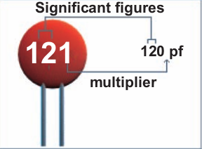
can be thought of as tiny rechargeable batteries—capacitors can be charged and
discharged. The amount of charge that a capacitor can hold is measured in Far-
ads or the letter F. However, 1F is too large for capacitors, so microfarads (μF)
and picofarads (pF) are used:

micro = 1/1,000,000 and pico = 1/1,000,000,000,000
So, 100,000pF = 0.1μF = 0.0000001F
Device Electrical Characteristics
An inductor or capacitor is an energy storage device; a capacitor’s current or an inductor’s voltage does not change instantaneously. Initial conditions can apply to both of these devices.
The ideal capacitor has zero conductance or infinite resistance and the ideal inductor has zero resistance or infinite conductance. Ideally, neither device dissipates heat (power). The total power consumed or delivered in an RLC is presented as a complex variable (phasor) with a real (dissipated power by resistors) and imaginary (reactive power ) component.
It should be mentioned that, a capacitor’s conductance (or an inductor’s resistance) only approaches zero and the rated component value (Farads for capacitors or Henries for inductors) may also vary. These variants in addition to EMI and environmental effects would require you to alter your design or analysis somewhat, depending on how critical they are to your design or model.
The Ideal voltage vs. current characteristics for the resistor, inductor and capacitor are shown below in Table 1.
source : PDHengineer.com
Course No E-6002
First Order RLC Circuits: Time Domain
Analysis
Thursday, November 3, 2011
Breadboard
Figure above shows a breadboard with holes connected in two long rows at the top and bottom, and columns of five linked holes elsewhere. Electronic components and wires can be simply plugged into the board in order to make any required circuit connections. The top and bottom rows act as power supply chan-
nels for the circuit.
Evaluation and Testing
Evaluation and testing is about making sure that the product stays on track with
the design specification. You should plan to evaluate and test your project at a
number of key stages of design and manufacture. These stages are referred to as
critical control points.
The critical control points for evaluation and testing an electronic prod-
uct are:
- Initial Design Phase: Check that you have used the correct value components, and that the various systems work together. These checks can be done using a computer-simulation package.
Breadboard Phase: Use the breadboard to check whether the circuit works properly. Test each part of the circuit using a millimeter or logic probe. - PCB Layout: Check that the components are in the correct positions and that you have used the optimum track layout. Make sure that the components are located neatly and that joints are well soldered.
- Manufacturing and Packaging Phase: After manufacture, check that the product conforms to its specification. During packaging, check that the product fits securely in the package, and that any conducting parts are insulated.
- Finally, the Analysis Phase: Look back over the design and making process. Analyze how well it went, noting any modifications and improvements you would make if you were to do it again. These notes are an important part of your design portfolio.
Monday, September 26, 2011
Capacitors
Measurement and Testing
Thursday, September 22, 2011
Resistor Combination
Resistors are in series if they are connected in tandem and carry exactly the same current. Resistors are arranged in a chain, so the current has only one path to take. The current is the same through each resistor. The total resistance of the circuit is found by simply adding up the resistance values of the individual resistors.
Resistors are in parallel if they are connected in the same nodes and have exactly the same voltage across their terminals. Resistors are arranged with their heads connected together, and their tails connected together. The current in a parallel circuit breaks up, with some flowing along each parallel branch and re-combining when the branches meet again. The voltage across each resistor in parallel is the same. The total resistance of a set of resistors in parallel is found by adding up the reciprocals of the resistance values, and then taking the reciprocal of the total.
Wednesday, September 21, 2011
TYPES OF RESISTORS
- Fixed Resistors
- Variable Resistors
Monday, September 19, 2011
Measuring Voltage
When connecting things, it’s always a good idea to use color coding to help keep track of which lead is connected to what. Use a black banana plug lead to connect the ‘common’ input of the meter to the ‘ground’ jack. Use a red banana-plug lead with the ‘V’ input of the meter.
(b) A drawing of the same circuit showing how the leads for a DMM should be connected when measuring voltage. Notice how the meter is connected in parallel with the resistor.
Kirchhoff’s Law
- Kirchhoff’s Current Law (KCL):
- Kirchhoff’s Voltage Law (KVL):
This law is also called Loop analysis
In this case the four components are resistances, but Kirchhoff’s Voltage Law can be applied no matter what components are connected in the closed circuit loop. The voltages across the four resistances comprising the circuit loop have been defined as V1, V2, V3,V4 and Kirchhoff’s Voltage Law allows us to write down an equationrelating these voltages.
To apply Kirchhoff’s Voltage Law correctly, we must make arbitrary choices about the direction of travel around the closed circuit loop and the contribution which the separate voltages make to the algebraic sum around the closed circuit loop. Suppose we travel around the loop in Fig. 2.2 in the clockwise direction (ABCD) and that voltages opposite to the direction of travel make a positive contribution to the algebraic sum. In travelling from A to B the voltage V1 is encountered and it is in a direction which is opposite to the travel. Therefore, V1 is a positive contribution to the algebraic sum. The same comment is true of V2, which is met when proceeding from B to C. However, travelling from C to D and back to A, the voltages V3 and V4 are encountered and in both cases the voltages are in the same direction as the travel, giving a negative contribution to the algebraic sum.
+ V1 + V2 - V3 - V4 = 0
Saturday, September 17, 2011
Multimeter
OHM’S LAW
voltage is applied.
the voltage (or pressure) across a resistor, the more the current, and the more the resistance for the same voltage, the less the current. In other words, the current is proportional to the applied voltage and inversely proportional to the resistance.
Taken from : Introductory Circuit Analysis 10th Edition by Boylestad
Thursday, August 25, 2011
What is capacitor?

- Charging

- Discharging

The use of capacitor in connection with other electronic devices:
-Reduces voltage fluctuation in electronic power supply
-A capacitor allows pulse signals to flow
-Made up an oscillator circuit if associated with inductive component
-Filtering specific frequency
-Provide electronic time delay
Wednesday, August 3, 2011
Resistor - Color Coding and Standard Value
E.g., the grey-red-brown-gold resistor is 820 Ohm Resistor.
The 555 Timer - Monostable Multivibrator
The output pulsewidth can be calculated by this formula